0
NodesIO-Link is fast becoming a well-established, worldwide communication solution in the sensor and actuator market. The adoption of IO-Link continues to grow across all automation networks and in a wide variety of applications.
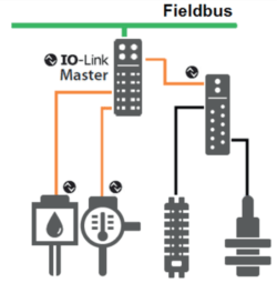
IO-Link is a serial, bi-directional point-to-point connection for signal transmission and energy supply under any networks, fieldbuses, or backplane buses. It is based on the familiar 3-conductor connection for a digital switching signal, in which the switching signal is issued as a serial telegram. With IO-Link, information can be exchanged in the form of a serial protocol between the I/O level and the field device.
The IO-Link system offers decisive benefits as a digital interface for connecting sensors/actuators.
Advantages:
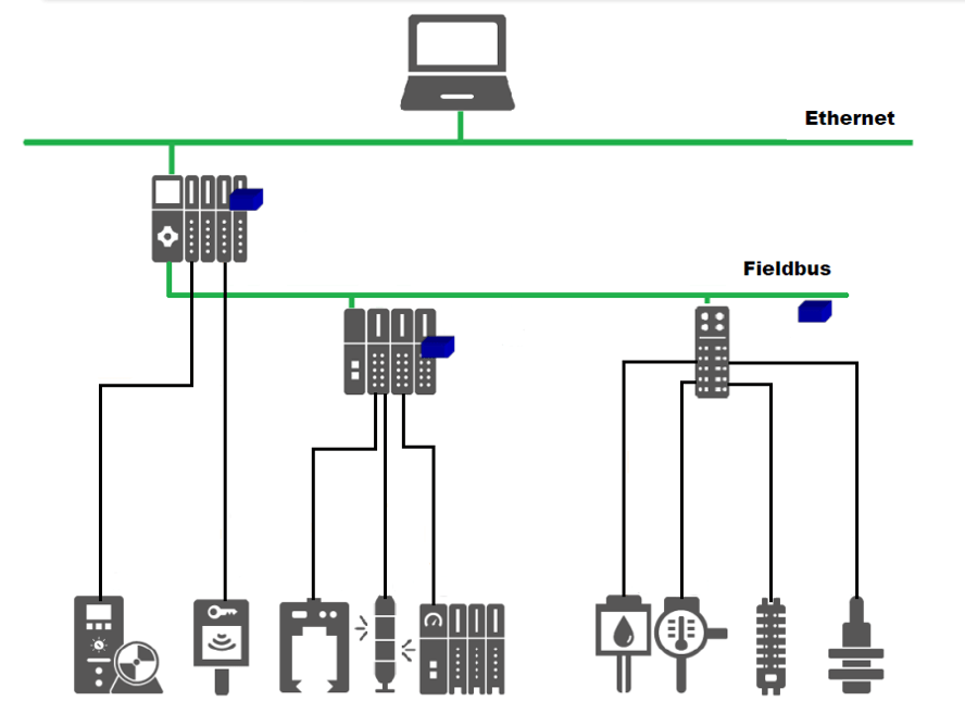
The Classic Automation Pyramid
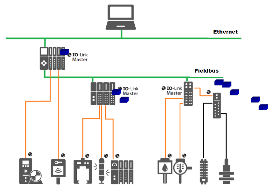
Automation Pyramid with IO-Link
The communication only reaches the I/O level or complex field devices. Simple standard sensors/actuators are not communicatively accessible
Simple sensors and actuators are communicatively accessible. Presence of bidirectional transmission of cyclic and acyclic data.
IO-Link Overview
IO-Link Components
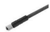
There are five basic elements in an IO-Link installation: IO-Link devices, IO-Link masters, 3-wire cables, IODD files, and the engineering tool.
IODD File: An electronic device description – the IODD file (IO Device Description) – is available for each device. The IODD stores a variety of information for system integration, such as communication properties, device data, device parameters, and illustration of the device.
IO-Link Configuration Tool: Used for project engineering and parameterization of the IO-Link system and the devices.
In order to configure the entire IO-Link system, configuration tools are required. The IO-Link configuration tools of the master manufacturers can read in IODDs. The main tasks of the IO-Link configuration tool include:
- Assignment of the devices to the ports of the master
- Address assignment (I/O addresses of the process data) to the ports within the address area of the master
- Parameter assignment of the IO-Link devices
Useful Resource: IODDfinder
IODDfinder is a non-proprietary central IODD database. It makes the current IODDs of the device manufacturers available and offers users an information and download platform.
Specification V1.0 vs V1.1
The technical definition of the IO-Link system is described in a specification of the IO-Link Community. Version 1.0 of the Specification was prepared in the first step. As a result of further development and the addition of functions to the IO-Link system, Version 1.1 was prepared.
The important additions in Version 1.1. are:
- Data backup of the device parameters
- Data transmission rate of 230.4 kbaud is mandatory for IO-Link master
- Process data width per port up to 32 bytes
If IO-Link devices of a different IO-Link specification are combined, the following must be noted:
- Only IO-Link devices according to V1.0 can be operated on V1.0 IO-Link masters.
- IO-Link devices according to V1.0 and V1.1 can be operated on the IO-Link master according to V1.1.
IO-Link Project
This section covers the four basic aspects of implementing IO-Link in an automation system: configuration, data access, setting updates, and device replacement.
Configuration of an IO-Link System
The IO-Link system is configured in two steps:
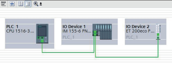
Integration into the automation system: In the configuration of the automation system or fieldbus, the IO-Link system is represented by the IO-Link master and integrated using the appropriate device description (e.g., GSD file for PROFINET). The IO-Link master itself can be a fieldbus node or a module of a modular IO system connected to the fieldbus. In both cases, the device description of the IO-Link master indicates the number of ports, the address range, and the module properties.
Engineering with the IO-Link configuration tool: The user needs the IO-Link configuration tool of the IO-Link master to configure the IO-Link system in detail and set its parameters. For configuration, they must set the parameters, diagnostics, and process values.
Data Access From the Automation System and HMI Device
Cyclic Data Exchange
The IO-Link data from the IO-Link master is placed on the address ranges assigned beforehand to exchange the cyclic process data between an IO-Link device and a controller. The user program on the controller accesses the process values using these addresses and processes them. The cyclic data exchange from the controller to the IO-Link device (e.g., IO-Link actuator) is performed in reverse.
Acyclic Data Exchange
Acyclic data, such as device parameters or events, are exchanged using a specified index and sub-index range. The controller accesses these using system mechanisms (e.g., in the case of online functions such as the reading out of the status). The use of the index and sub-index ranges allows targeted access to the device data (e.g., for reassigning the device or master parameters during operation).
Programming the User Program
First, the user must focus on configuring and assigning the parameters of the IO-Link system and its integration in the overall automation system. After, it is also necessary to write the user program of the controller. Controller and device manufacturers offer IO-Link function blocks to assist users in the programming of acyclic access.
Changing and Backing Up Device Settings During Operation
Device settings can be changed during operation. These settings (parameters) take effect on the device and are saved in the device. Parameters can be changed during plant operation by the:
- Engineering tool (e.g., when commissioning the plant)
- User program of the PLC
- HMI (by the plant operator for a batch changeover, process optimization)
- Local operator input on the device (through a local operator control unit on the device)
Device Parameter Back-up
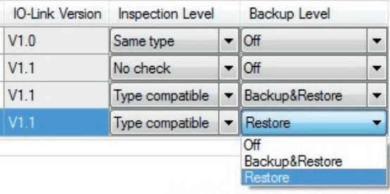
The parameters that are set during engineering or changed during plant operation can also be saved in the master. This backup is carried out according to the data backup setting of the master ports. The following settings are available:
- NONE: No backup of the device parameters is made in the master.
- BACKUP/RESTORE: After every change of the device parameters, a backup of these data is made automatically in the master.
- RESTORE: No automatic backup of the device parameters is made in the master.
Replacement of a Device or Master During Operation
Device Replacement
Device replacement during operation is a common need and must not cause an extended downtime of the factory. When the backup function of the master is used, the master automatically provides the saved parameters to the new device after replacement. The following cases must be distinguished here:
- BACKUP/RESTORE: The new device takes up the same behavior as the replaced device because the master had stored the last parameter change in a “Backup.”
- RESTORE: The new device takes up the behavior according to the parameters saved in the master at the time of the last backup.
It must be generally noted that sensors often require field calibration. This information is not part of the backup; such data must be restored after device replacement by performing another field calibration.
Master Replacement
The replacement of a master during operation represents a less common scenario. Because the master has both its own configuration and parameter data as well as the data of the connected devices, these data can be backed up in the PLC and reloaded on the newly installed master. PLC providers offer methods (e.g., function blocks) that support the upload and download of a complete master backup.
Additional IO-Link Functionality
IO-Link Diagnostics
Smart sensors equipped with IO-Link can communicate their status via the IO-Link master to the PLC. Before processes come to a halt, you’ll know immediately if a sensor needs to be replaced, requires maintenance, or is experiencing an error. The diagnostic capabilities give you the ability to optimize machine maintenance schedules and diagnose problems with a specific sensor without shutting down the entire line or a piece of equipment.
IO-Link acts as a factory’s eyes and ears, providing insights into processes that allow for decision-making to decrease downtime. If a sensor experiences an electrical short, for example, IO-Link sends alerts, pinpoints the sensor’s exact location, and shares diagnostic information in real-time so the cause of the issue is known.
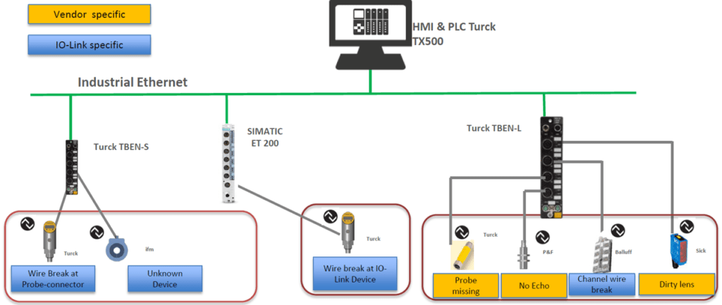
There are IO-Link specific diagnostics and vendor-specific diagnostics. For example:
- IO-Link Master diagnostics
- Wrong device
- Wire break
- Failed data storage
- Invalid process data
- IO-Link Device diagnostics
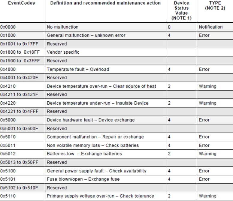
- IO-Link specified events: defined Eventcodes by specification
- Vendor independent diagnosis: vendor-specific events
IO-Link Safety
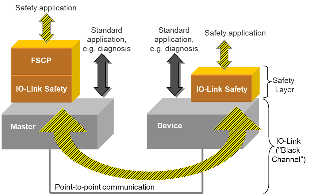
IO-Link Safety is an extension to IO-Link by using an additional safety communication layer on top of both the master and the device sides, thus becoming a functional safety (FS) master and an FS device. IO-Link safety has been approved by TÜV-SÜD.
IO-Link Safety can support any type of FS-Device, such as a sensor, actuator, or complex mechatronic. It also allows for new kinds of safety applications, for example, through local safety logic within the FS-Master in conjunction with higher-level safety functions. Within the system, safety and non-safety data transmission coexist. The point-to-point communication nature of IO-Link Safety eases the user experience in terms of installation and configuration.
IO-Link Black Channel
A functional safety communication protocol (FSCP) like PROFIsafe follows the “Black Channel” principle. PROFIsafe is used as a carrier for particular types of messages containing safety process data and additional safety code.
IO-Link Safety also follows the Black Channel principlet. The IO-Link safety communication layer is located on top of the FS-Device and FS-Master stack.
Benefits:
Profiles
The device profiles specify the data structure, data contents, and basic functionality of a family of IO-Link devices. Different devices from the same IO-Link device profile exhibit a uniform user view, and identical access by the program on the controller.
IO-Link has defined the following device profiles:
- Binary switching sensors: The profiles for switching sensors are appropriate for simple switching applications such as presence detection.
- Digital measuring sensors: The digital measurement profiles are designed for measuring sensors that can provide the values based on a physical unit such as temperature or pressure. These profiles make it possible to integrate IO-Link sensors without special knowledge of the sensor used.
- Devices with uniform system behavior: The device profile for uniform system behavior defines minimum device identification, diagnostics, and event data. IO-Link devices that support this profile offer a uniform minimum degree of integration of the system into the controller. This profile is the basis for all other device profiles.
IO-Link Wireless
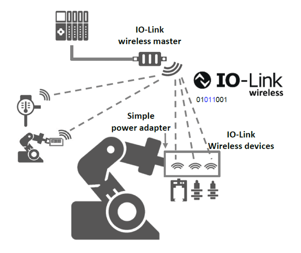
IO-Link Wireless defines wireless network communication between sensors, actuators, and controllers (PLC) in automation environments. It is designed to provide a similar level of performance and backward compatible interface as a cable connection, ensuring a seamless migration from wired to wireless systems.
Multiple devices can communicate with an IO-Link Wireless master at the same time. With IO-Link Wireless, all data can be transferred from devices (process data, parameters, and diagnostic data).
Properties:
Use Cases
Use cases for the IO-Link Wireless can be found in different applications. This new technology contributes to the general effort to reduce wiring and cabling. Also, it lowers the cabling requirements in harsh environments and as a result, minimizes the number of possible errors. Besides, IO-Link Wireless can simplify the installation of components that are difficult to access in the application.

Robot Arm: Cable Strain
The cables in a robot are stressed because of its permanent movement. Wireless solutions to reduce the cabling can help to reduce downtime.
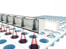
Conveyor Belt: Reduction of Cabling
A lot of sensors are used to check the transported products in sensor bridges. IO-Link Wireless can help to reduce the cabling of these sensors.

Hygienic Area: Reduction of Contamination
In hygienic areas, any kind of contamination must be avoided. IO-Link Wireless helps minimize exposure to sensors for installation and diagnostics.

