There are two flavors of PROFIBUS: PROFIBUS Decentralized Peripherals (DP) and Process Automation (PA). Each type targets different applications.
PROFIBUS PA is used in process automation. The physical layer of PROFIBUS PA is Manchester Encoded Bus Powered (MBP), and the physical layer for PROFIBUS DP is RS-485. Even though a different physical layer is employed, PROFIBUS PA is the same protocol as PROFIBUS DP.
PROFIBUS DP and PA are widely used in industrial automation. The next sections will give you an overview of each.
PROFIBUS DP vs. PA
PROFIBUS links controllers and control systems with field devices and also enables simultaneous consistent data exchange with superordinate systems. PROFIBUS is the fieldbus-based automation standard of PROFIBUS and PROFINET International (PI).
PROFIBUS consistency is based on the standardized “PROFIBUS DP” communication protocol, which supports various applications in factory automation, process automation, motion control, and safety-related tasks. This integration makes planning, installation, commissioning, and maintenance easier. PROFIBUS DP employs the RS-485 physical layer. The easy-to-use and cost-effective RS-485 transmission technology is used for tasks that require a high transmission speed but which do not require explosion protection (intrinsic safety).
Process Automation environments, while typically requiring slower procedures, might also be characterized by explosive or hazardous environments. In such applications, PROFIBUS PA is a suitable solution. PROFIBUS PA can be deployed in hazardous environments since its physical layer: MBP, is intrinsically safe.
It is important to note that even though a different physical layer is employed, PROFIBUS PA is the exact same protocol as PROFIBUS DP. MBP only transmits at one speed: 31.25 kbit/s, which is plenty for process applications. A significant departure, however, is that power and data are transported via the same cable. As such, there are rules regarding network topology that must be followed.
PROFIBUS DP and PA Topology
If RS-485 transmission technology is used, all field devices are typically connected in a line structure with up to 32 nodes in one segment. The beginning and end of each segment are provided with active bus termination and power. If there are more than 32 nodes or the network span is being extended, repeaters must be used to link the networks.
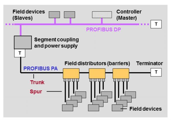
If MBP transmission technology is used (in process automation), basically, any topology is permissible. Linear and tree structures and combinations of both are thus possible. In practice, the “trunk & spur topology” has established itself as the de-facto standard, as it is especially clear and well-laid-out.
Coupling RS-485 and MBP Transmission Technology
The vast majority of a PROFIBUS network is usually based on RS-485 (PROFIBUS DP). The implementation of PROFIBUS PA is typically limited to certain subsegments of a system, such as a group of field devices in a hazardous area. Connecting PROFIBUS DP and PA segments is a common practice.
The connection of PROFIBUS PA subsegments to the RS-485 PROFIBUS DP segment is carried out using segment couplers or links. Segment couplers are transparent from the standpoint of the bus protocol. The MBP segment devices are directly visible on the DP side, and the segment coupler does not require configuration. Links, on the other hand, are intelligent and map all devices connected in the MBP segment as a single device in the RS-485 segment.
For a complete overview of PROFIBUS DP and PA, take our free training: PROFIBUS Online Training Course.