

This article lists the top five mistakes made in PROFIBUS networks and gives you troubleshooting information and tips on how to prevent them.
Wrong cable

Do not utilize telephone or other consumer-market off-the-shelf cables in a PROFIBUS network. Such cables are not built to survive in industrial facilities where PROFIBUS is used. PROFIBUS installations should employ shielded twisted pair cables that meet PROFIBUS guidelines. Dozens of vendors offer PROFIBUS cables which often come with a purple jacketing and comply with ruggedized specifications that have been set by PI.
Improper distance for baud rate
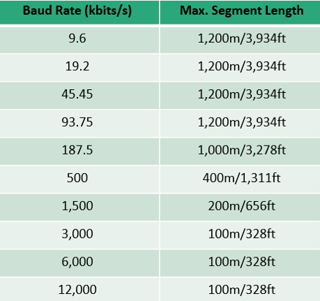 PROFIBUS DP networks can run at different baud rates, depending on the application. The higher the baud rate, the shorter the recommended maximum length for cable segments. Utilizing proper cable segments prevents significant signal attenuation and distortion.
For example, at 1.5 and 12 Mbit/s baud rates, the maximum recommended segment length is 200m and 100m, respectively.
Never exceed the maximum recommended cable length. Always check your installation against the PROFIBUS Installation Guidelines and confirm that cable lengths are appropriate.
PROFIBUS cable installed too close to power cables
PROFIBUS, like any digital network, is susceptible to electromagnetic interference.
To prevent data corruption due to EMI, avoid running data and power cables right next to each other. Maintain the separation distances specified in the PROFIBUS Installation Guidelines and if they need to cross one another, it should be at right angles.
If data cables need to run in an area where very strong interference is unavoidable, consider fiber optic cables instead of copper, as they are immune to electromagnetic interference.
Improper shielding and grounding
The PROFIBUS Installation Guideline recommends that cable shielding be grounded at multiple points or both ends of a segment. This protects against high-frequency interference and provides a low impedance path to ground in case of any pickup. Ungrounded shielding is ineffective.
With PROFIBUS it’s easy: simply ensure that connectors are properly installed. That’s it. From there, nearly all devices provide continuity from the metal shroud on the plug, through the socket, to a ground lug or metallic DIN rail connection.
Lack of or improper termination
Finally, the most common problem in PROFIBUS networks is… lack of or improper termination.
PROFIBUS networks must have termination resistors engaged at the beginning and end of each segment in order to minimize signal reflections. It is easily implemented via built-in switchable termination in connectors, in devices, or via an active termination box.
 As you can see, most of the problems that crop up in PROFIBUS networks have nothing to do with the protocol itself -but the installation of the network.
We recently launched a PROFIBUS Online Training Course that covers a complete overview of PROFIBUS DP and PA network design, configuration, installation, commissioning, maintenance, and troubleshooting. You can take the course at test.local/profibusonline