
Fiber optic cables offer specific benefits over copper. They are usually implemented in areas with electromagnetic interference or significant ground potential differences. Fiber optic connections can completely remove problems caused by electromagnetic interference and ground equalization currents flowing in copper cable shields/screens. Some benefits of optical fibers over copper cables are:
- Optical fiber cables usually cover longer distances as compared to copper cables (up to 2 orders of magnitude).
- Fiber optics cables provide total electrical isolation between plant areas.
- Fiber optics cables are totally immune to electromagnetic interference.
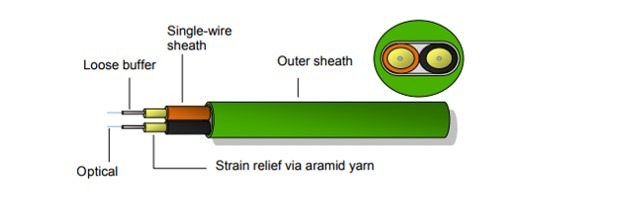
The PROFINET fiber optic cable schematic below shows the general structure of such a cable, which consists of two parallel wires. The wires are ready for direct assembly of connectors. The orange wire has printed directional arrows to facilitate the assignment of wires to the transmit and receive connections.
The table below lists the minimum requirements for a PROFINET fiber physical layer. The requirements for a fiber optic interface are nearly the same as those for a copper interface, but the second physical layer feature requirement varies.
| Physical Layer feature | IEEE Standard |
| MAC Address | 802-2001 |
| 100Base FX Full Duplex Transmission | 802.3-2008 (Clause 24,26) |
| MAC Bridging and Switching functions | 802.1D-2004 |
| Support VLAN Priority tags | 802.1Q-2011 |
| LLDP Neighborhood Detection | 802.1AB-2005 |
Fiber Optics Types and Parameters
Fiber type selection should be based on the requirements given by the automation project. In general, there are two types of optical fiber cables: Type B and Type C. Type B optical fiber cables are for stationary or flexible use. Type C optical fiber cables are used mainly for special applications e.g. permanent movement or vibration or torsion.
Four different fiber classes can be employed when using optical fibers for PROFINET. Those four classes are Plastic optical fiber (POF), Glass fiber (multi-mode), Glass fiber (single-mode), and Glass fiber with a plastic jacket (hard-coated silica fiber (HCF) or plastic-coated fiber (PCF)). The table below summarizes some fiber class factors:
| Fiber Class | Transmission path (typical values) |
Max PROFINET end-to-end link attenuation |
Wavelength | Core diameter | Main cable connectors |
| POF | Up to 50 m | 12.5 dB | 650 nm | 980 µm | SC-RJ |
| HCF/ PCF | Up to 100 m | 11.3 dB or 6.3 dB | 1300 nm | 200 µm | SC-RJ |
| Multi-mode | Up to 2000 m | 10.3 dB | 1310 nm | 50 or 62.5 µm | LC |
| Single-mode | Up to 1400 m | 4.75 dB | 650 nm | 9 to 10 µm | LC |
Read the full white paper: PROFINET Cabling: Overview and Implementation Considerations
PROFINET Cabling: Overview and Implementation Considerations
-Nelly Ayllon